Panel design wizard
Design PLC, MCC and distribution panels, wall-mounted enclosures, control desks, field junction boxes and push-button boxes in eight steps: enclosure body, door devices, rails and cable ducts, equipment, heat calculation and bill of materials. The wizard creates a 3D scene, a 2D view screen and a bill of materials screen.
The panel design wizard designs a panel step by step: enclosure and sections, devices on the door, DIN rails and cable ducts, circuits and devices, heat calculation and bill of materials. The preview on the right is updated with every change. At the end, the wizard builds a 3D scene, a 2D view screen and a 2D bill of materials screen. The objects it uses are the panel components of the library; they can also be changed manually in the editor afterwards.
Opening the wizard
Select Tools›Panel design wizard…. The wizard opens with the last design in the project; if there is no design, it starts with a new PLC panel. Use the Design list at the top to switch to another design in the project or to + New design. While the wizard is open, F1 opens this topic.
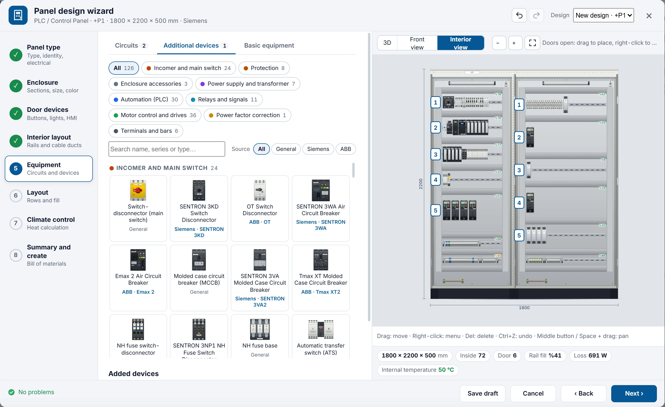 1234567
- Steps — eight steps; a red dot on a step with problems.
- Circuits / Additional devices / Basic equipment — the three tabs of the Equipment step.
- Catalog — function categories, search and Source filter.
- Preview — 3D, Front view, Interior view.
- Undo / Redo — changes in the wizard.
- Summary — dimensions, number of devices, rail fill, loss, internal temperature.
- Bottom bar — first problem, Save draft, Cancel, Back / Next.
- Preview tabs: 3D, Front view (doors closed) and Interior view (doors open; mounting plate, rails, ducts). Each step opens the tab that suits it; you can switch to any tab. The 3D tab has the buttons Front view, Perspective, Close-up inside, Fit and the Doors open / Doors closed button that opens and closes the doors.
- Footer: outer dimensions, number of devices inside the panel and on the door, average rail fill, the power loss included in the calculation (with simultaneity) and the internal temperature without cooling.
- Bottom bar: on the left, the first problem and the number of remaining problems (click it to go to the step of the problem; if there are no problems, No problems). On the right, Save draft, Cancel, ‹ Back, Next ›; in the last step, Create. A red dot appears on the number of a step with problems.
- Undo / Redo: the two buttons in the title bar or Ctrl+Z / Ctrl+Y. Every change in the wizard can be undone (up to 200 steps). In a text field these keys act as the field's own undo.
- Closing: Cancel, × or Esc. If there are unsaved changes, you are asked to choose Save draft and close, Close without saving or Continue. Save draft writes the design to the project without creating screens.
Steps
| Step | What is set |
|---|---|
| Panel type | Type: PLC / Control Panel, MCC panel, Distribution Panel, Wall-Mounted Enclosure, Control Desk, Field Junction Box, Push-Button Enclosure. Brand (below), Ready-made starts, Identity (Panel name, Panel code), Electrical (supply system, control voltage, rated current, short-circuit rating, degree of protection, internal separation for MCC) and Environment. |
| Enclosure | For a floor-standing panel, the Sections table (at most 12 sections; width 300 – 1200 mm, type, door), height, depth, plinth and, for an MCC, the top busbar compartment. For wall-mounted enclosures, control desks and junction boxes, their own dimensions and mounting height; for a push-button enclosure, the number of holes (1 – 5) and their arrangement. Color (RAL shades or a custom color). The door hinge is in this step. |
| Door devices | Door leaf selection, Ready-made groups (motor control, emergency stop + reset, Hand – 0 – Auto, status lamps, operator panel, main switch handle, measuring instruments, labels …), Add a single device (door catalog), device labels and options, Arrange this door automatically. |
| Interior layout | Preset layouts (Standard, Dense wiring, Compact, No ducts), horizontal and vertical cable duct dimensions, rail profile (35 × 7.5 / 35 × 15), device–duct clearance, plate edge margin, cable entry area at the bottom, spare space per rail (0% – 40%), Put each section group on its own row, Add spare rails in the free space. At the bottom, a summary of the mounting plates. |
| Equipment | Circuits: motor (direct-on-line, star – delta, with frequency converter, with soft starter), PLC system, distribution outputs, power factor correction, energy metering. A circuit adds all the devices and terminals it needs, plus the optional door controls, in one go. Additional devices: a single device from the catalog. Basic equipment: main switch, door-operated main switch, surge arrester, phase monitoring relay, supply terminals, 24 V DC power supply, service socket, panel lighting, PE busbar, control fuses. |
| Layout | The rows and fill bars of each section, spare space, the Manual layout state, Back to automatic layout, Deleted devices (n)…. Devices are arranged from top to bottom in category order (incomer → distribution → PLC → relay → motor); the terminals are at the bottom of the section. |
| Climate control | Ambient and target temperatures, enclosure material, simultaneity, Installation type, calculation, recommendation and Decision (Apply recommendation, Choose manually, No climate control), editable Loss table. |
| Summary and create | Summary cards, Warnings, Bill of materials and Export to Excel, To be created, Delete design from project. |
A push-button enclosure has only the Panel type, Enclosure, Door devices and Summary and create steps; a field junction box has no Interior layout step.
Ready-made starts (11 examples): Small PLC panel, Pump station, PLC + drive panel, MCC with 5 sections, Sub-distribution panel, Power factor correction panel, Wall-mounted control panel, Operator desk, Field junction box, Start / stop box, Emergency stop box. Selecting one fills all settings with the example (if the design already has content, you are asked to confirm first); the selected brand does not change. Changing the panel type also resets the enclosure, door devices, circuits and equipment to the defaults of the type.
Brand
In the Panel type section of the Panel type step, select the Equipment brand: Generic, Siemens or ABB. This selection is only the default brand of the devices added automatically by circuits and basic equipment. A device that has an equivalent is placed with that brand's library object (contactor → SIRIUS 3RT2 Contactor or AF Contactor, PLC → S7-1500 / S7-1200 or AC500 …). Below the section, the number of devices placed with a brand object and the number that remain generic are shown.
- The model of each device can then be changed individually: right-click › Change… (below). A device you added from the catalog stays as you selected it; the brand selection does not affect it.
- Items that have no equivalent in the brand remain generic, for example the enclosure body and mounting plate, rails and ducts, terminals, busbar and PE bar, fan / air conditioner / heater / thermostat, lighting and socket, auxiliary relay, control transformer, filter / reactor / braking resistor, power factor correction capacitor, labels and door accessories. With Siemens selected, the 22 mm door devices and operator panels of 15" and larger also remain generic; with ABB selected, the 12", 19" and 21" operator panels, the 40 A power supply, DC UPS, Ethernet switch and interface relay block.
- The bill of materials shows the brand and series name (Siemens SENTRON 3KD · Switch-disconnector 3P 125 A). The order number is not shown. The objects carry no logo or brand lettering (Siemens and ABB panel equipment).
Enclosure and door hinge
Select the hinge side of a single-leaf door. On a floor-standing panel, use Hinge on left / Hinge on right for each section in the Hinge on left column of the Hinge on right table; on a wall-mounted panel and a control desk, use Door hinge, on a junction box Cover hinge (Left / Right).
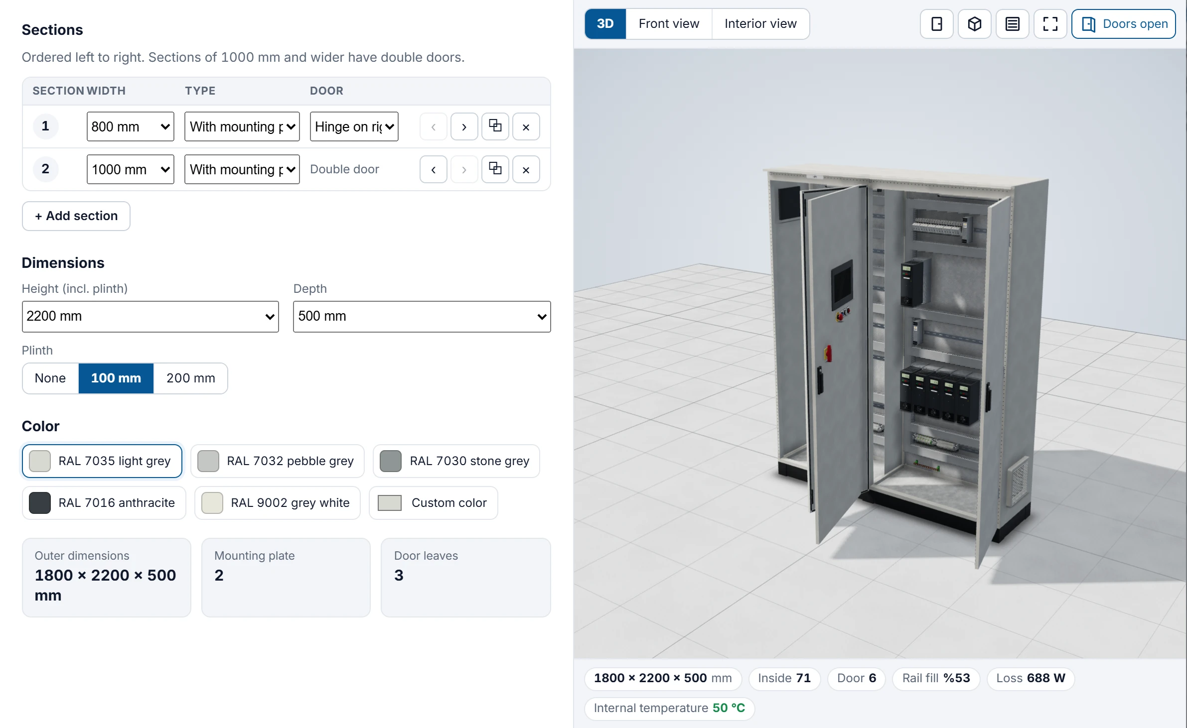 1234
- Sections — width, type, door; reorder, duplicate, delete.
- Hinge — left or right on a single-leaf section.
- Double door — 1000 mm and wider; hinges on the outer edges.
- Doors open / closed — in the 3D preview.
- Sections of 1000 mm and wider have double-leaf doors; the hinges are on the two outer edges and no choice is shown (the table shows Double door, the wall-mounted enclosure and the operator desk show Double door: hinges on the outer edges). The drawer section of an MCC has no door. On an operator desk of 1000 mm and wider, the lower cover is double-leaf.
- The hinge is drawn on the same side in 2D, 3D and the realistic model; the devices on the door swing with the door.
- With a right-hand hinge, the automatic arrangement moves the main switch handle to the lock side, that is, to the left edge. Door devices that you placed manually in the preview stay in place and are not mirrored.
Door elements
- Devices are added to the selected door leaf. In a panel with several leaves, select the leaf with the leaf buttons at the top or by clicking the area of the leaf in the preview.
- While you are in this step, you place the devices in the Front view by dragging them on a 5 mm grid; they stay where you drop them. Arrange this door automatically or the ↺ in the row deletes the manual position.
- In automatic arrangement, the labels and HMI are at the top, the control groups below them row by row, the main switch handle on the lock side and the vents at the very bottom.
- For a floor-standing panel, the preview shows the 600 – 1700 mm ergonomic band. A control device whose center is below 600 mm or above 1900 mm gives a warning. A red start button (START, BAŞLA …) or a green stop button (STOP, DUR …), recognized by its label, also gives a warning (IEC 60204-1). A device that extends beyond the door surface is an error; overlapping devices are a warning.
- The door controls of the circuits are in the From circuits list; their settings are in the circuit in the Equipment step. In a panel with several door leaves, Door for circuit controls selects their leaf.
- In a push-button enclosure, only 22 mm control and signaling devices can be selected; the holes are filled in order.
Catalog, Change… and Properties…
Equipment › Additional devices and Door devices › Add a single device are catalogs. The catalog shows generic, Siemens and ABB types in a single list.
- The interior catalog is divided into function categories: Incomer and main switch, Protection, Enclosure accessories, Power supply and transformer, Automation (PLC), Relays and signals, Motor control and drives, Power factor correction, Terminals and bars. The door catalog contains Control and signalling, Panels and meters, Labels and accessories.
- The search box searches name, series and type. Source filter: All (default), General, Siemens, ABB. The source is shown below each tile (Siemens · SENTRON 3KD, General).
- A click adds the device and places it automatically (if the same device already exists in an automatic section, its quantity increases); a door device is placed on the selected leaf. You can also drag the tile onto the preview: a device dropped on the Interior view is pinned where it is dropped (a rail-mounted device snaps to the nearest rail), and a door device dropped on the Front view is placed on the leaf and at the position where it is dropped.
- The options, quantity and section of an added device are changed in the list.
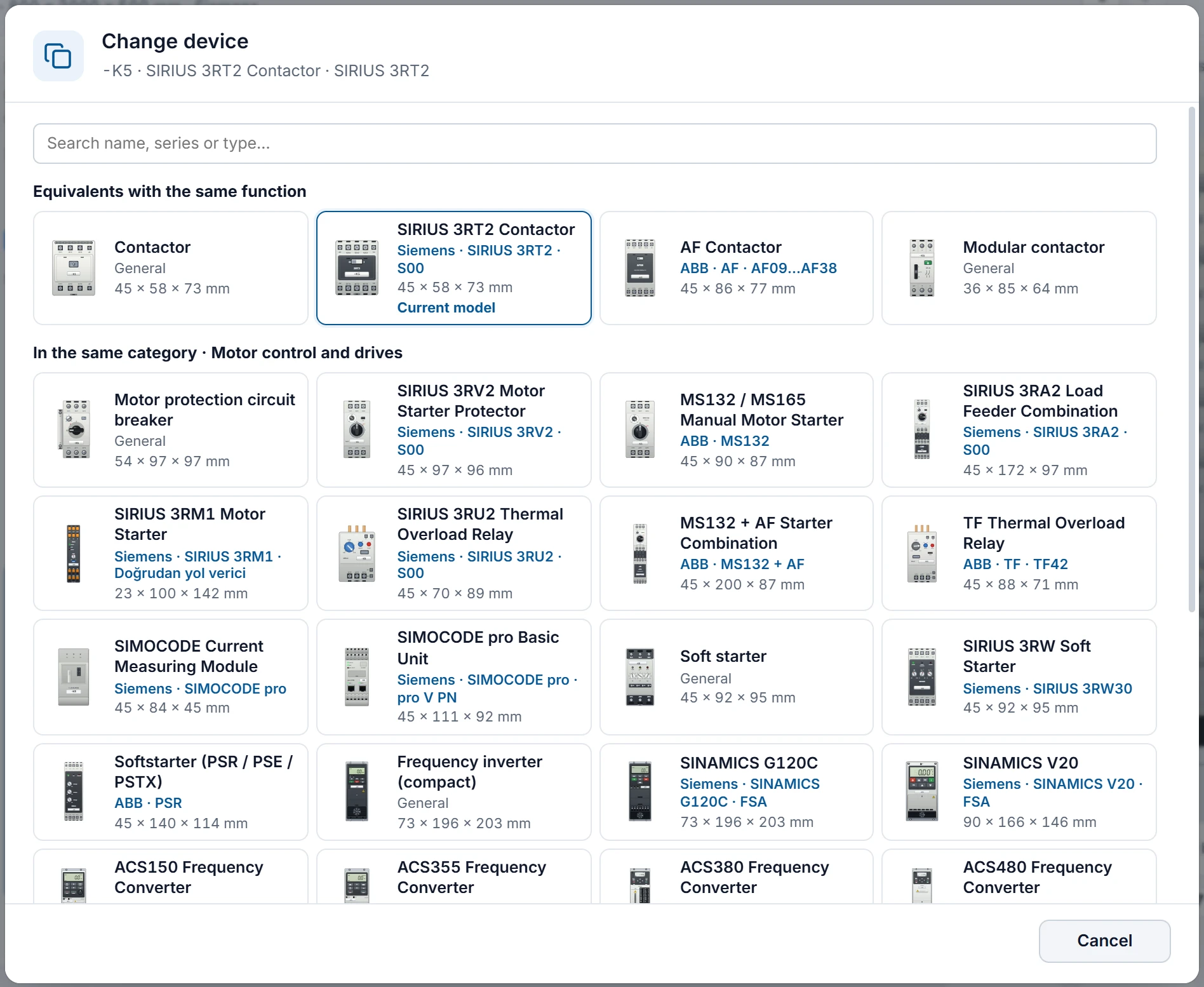 1234
- Search — name, series or type.
- Equivalents with the same function — generic, Siemens and ABB models.
- Current model
- In the same category — the other devices in the category.
Change… (right-click, ⇄ in the list or the button in the bottom panel) changes the model of any device in the plan, whether it comes from a circuit, from the basic equipment or from the catalog. At the top, Equivalents with the same function are listed, below them In the same category (on the door, Other door devices). Options such as size and current are carried over to the new model as far as possible; the device code, the category and the circuit link do not change. If you changed the model of a device that comes from a circuit or from the basic equipment, the window also shows the Reset to default button. Properties… (⚙) opens the options of the device type (except model, state and color; a door device also has its text); the thumbnail and the dimensions are updated according to the selection. The model of terminals, rails and ducts cannot be changed.
Editing in the interior view
The Interior view can be edited directly in every step (in panels with a section that has a mounting plate; not in the push-button enclosure). The panel below the preview shows the selected device, rail or duct; when nothing is selected, it shows a short help text.
Moving a device
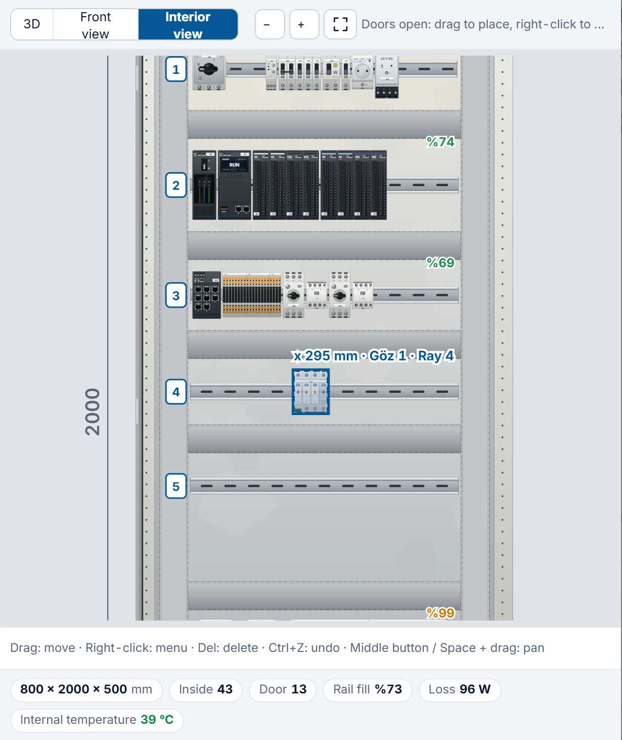 1234
- Ghost — where the device will be dropped (5 mm grid, magnet).
- Position — x from the left edge of the plate, section and rail.
- Rail handle — numbered; dragging it changes the rail spacing.
- Bottom panel — selected device / rail / duct; short help when nothing is selected.
- Drag the device: slide it along the same rail, or drop it on another rail or in another section. A DIN-rail device snaps to the center line of the rail; a device screwed to the plate stays free on the plate. The position is on a 5 mm grid. The device snaps to the edge of its neighbor and to the start of the rail when it comes close (magnet). While Alt is held down, it moves in 1 mm steps without the magnet.
- While you drag, a semi-transparent ghost and the text x … mm · Section … · Rail … are shown (for a device placed freely on the plate, also y … mm). x and y are measured from the left / bottom edge of the plate. A place where the device cannot be dropped is shown in red.
- The device you drop is fixed (small mark in its top right corner). Devices that are not fixed flow into the gaps on the rail; a device that does not fit moves to the rail below.
- A device dropped onto a fixed device is pushed to the nearest free position on the same rail. If there is no room on the rail, the device appears red where it was dropped and an error appears under Warnings. A free device on the plate stays where you want it; if it overlaps another device or a duct, or extends beyond the plate, it gives an error in the same way.
- Several devices: Shift or Ctrl + click adds to / removes from the selection; dragging in an empty area draws a frame and selects the devices inside it. The selected devices are moved together.
- Right-click › Release to automatic or the Fixed check box in the bottom panel removes the pinning. Move to next free spot moves the device to the right on the same rail or, if there is no room, to the first free spot on the following rails.
- On the first manual operation in a section, the current layout of that section switches to manual layout as it is; the first operation does not move the other devices.
Rails and ducts
- Drag the rail by the numbered handle on the left or by an empty spot on the rail. The devices on it move with the rail; the cable ducts between it and the neighboring rails shift in proportion to the spacing. The label shows the center line and the distance to the rail above / below.
- The handles at both ends of the selected rail change the rail length. The bottom panel shows Center line, To upper rail, To lower rail and Length in mm (spacing from center line to center line; length at least 50 mm). The same fields are in the right-click › Spacing… window.
- Adding rails: + Rail above / + Rail below (in the middle of the gap to the neighbor) or Add rail here in an empty area. Distribute evenly (at least three rails): the top and bottom rails stay in place, the ones in between are arranged with equal spacing.
- When you delete a rail that has devices on it, you are asked: Delete the devices too or Leave devices to automatic layout.
- Horizontal cable ducts can also be dragged. Ducts can be added and deleted; their width can be set to 25, 40, 60, 80 or 100 mm.
Deleting, restoring, automatic layout
- When a device added from the catalog is deleted, the quantity of its entry is reduced or the entry is deleted. A device you added to the door yourself is removed from the list.
- When a device that comes from a circuit or from the basic equipment is deleted, it is removed from the plan, the heat calculation and the bill of materials, and goes into the Deleted devices list. Right-click in an empty area › Deleted devices (n)…, or the button in the Layout step, opens the list; Restore / Restore all puts the device in a free position.
- Back to automatic layout… removes the manual positions, rails and ducts; the devices are arranged automatically again. Deleted devices stay deleted.
- When you add or delete sections or change their order, manual layouts move together with their sections.
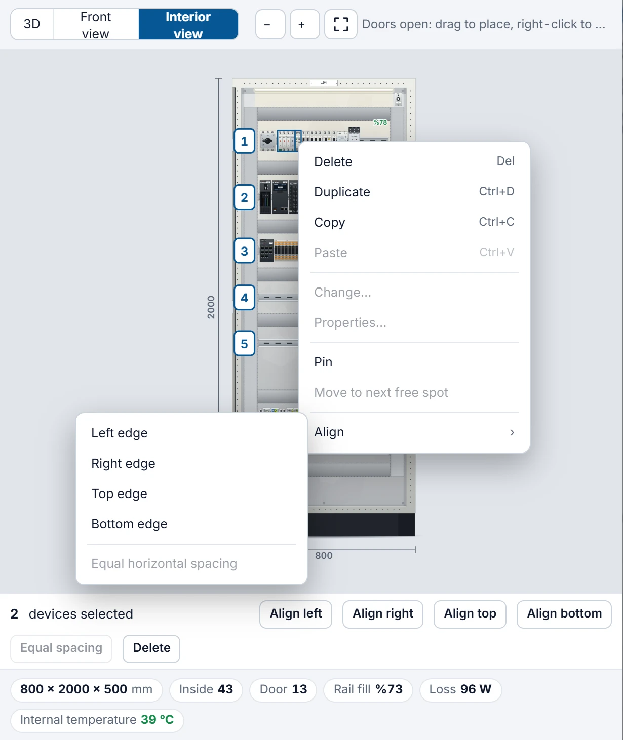 123
- Selected devices — Shift / Ctrl + click or selection frame.
- Device menu — delete, duplicate, copy, change, pin …
- Align — edges and equal horizontal spacing.
Right-click menus
| Where | Menu |
|---|---|
| Device (Interior view) | Delete, Duplicate, Copy, Paste · Change…, Properties… (single device) · Pin or Release to automatic, Move to next free spot · with several devices Align › Left edge, Right edge, Top edge, Bottom edge, Equal horizontal spacing (at least three devices) |
| Rail | Add rail (above), Add rail (below), Delete rail · Push devices to the left, Spacing…, Distribute rails evenly · Add duct (above), Add duct (below) · Paste |
| Cable duct | Delete duct, Duct width › 25 / 40 / 60 / 80 / 100 mm |
| Empty area | Paste, Select all · Add rail here, Add duct here, Distribute rails evenly · Back to automatic layout…, Deleted devices (n)… |
| Door device (Front view) | Delete, Duplicate, Copy, Paste · Change…, Properties… · if placed manually Back to automatic position |
| MCC drawer, air circuit breaker | Change…, Properties… |
Keyboard and mouse
| Key / mouse | What it does |
|---|---|
| Drag | In the interior view: device, rail, rail end, duct; on an empty area, frame selection. In the front view, during the Door devices step: door device. |
| Alt + drag | Without grid (1 mm steps), without magnet. |
| Shift / Ctrl + click | Adds the device to / removes it from the selection (devices can also be added with a frame). |
| Delete / Backspace | Deletes the selected devices, rail, duct or door device. |
| Ctrl+D | Duplicates: the copy is placed immediately to the right. |
| Ctrl+C / Ctrl+V | Copies / pastes. Pasting places the copy under the cursor; if the cursor is not in the preview, to the right of the copied item. A door device is pasted onto the door leaf under the cursor. |
| Ctrl+A | Selects all movable devices in the interior view. |
| ← → | Moves the selected device by 1 mm (10 mm with Shift). |
| ↑ ↓ | Moves a rail-mounted device to the rail above / below; moves a free device on the plate, the selected rail or duct by 1 mm (10 mm with Shift). |
| Arrow keys (Front view) | Moves the selected door device by 1 mm (10 mm with Shift). |
| Ctrl+Z / Ctrl+Y | Undo / redo (Ctrl+Shift+Z also redoes). In a text field, the field's own undo works. |
| Esc | Closes the menu, cancels dragging, clears the selection in the interior view; if none of these applies, closes the wizard. |
| Wheel · double-click | Zooms around the cursor · a double-click on an empty area fits the view (there are also −, + and fit buttons). |
| Middle button or Space + drag | Pans the zoomed preview. |
While the wizard is open, the Studio shortcuts F2, F5, F7, F9, Ctrl+O and Ctrl+N do not work; the project is left untouched.
Heat calculation (IEC TR 60890)
The Climate control step adds up the typical power losses of the devices, multiplies them by the diversity factor and calculates the effective surface area (A) of the enclosure according to the installation type with the formulas of IEC TR 60890. The internal temperature without cooling is found with Ti = Ta + P / (k · A) (k: heat transfer coefficient of the enclosure material). If Ti exceeds the target:
- If the ambient temperature is at least 5 K below the target, the panel is indoors and the degree of protection is up to IP55, a filter fan is recommended: required air flow
V = 3,1 · (P − k·A·ΔT) / ΔT. If the required air flow exceeds 1100 m³/h, if there is no fan that fits the panel depth, or if these conditions are not met, an enclosure air conditioner is recommended (roof-mounted air conditioner only for a floor-standing panel):Q = P − k·A·(Ti − Ta). - If the lowest ambient temperature is below the minimum internal panel temperature, a heater is recommended; outdoors, a heater of at least 30 W and a hygrostat are added. When there is a fan or a heater, a thermostat is also added.
The recommended fan, air conditioner, heater, thermostat and their fuses are placed inside the panel and on the enclosure and are added to the bill of materials. With Choose manually you select the fan size and quantity, the air conditioner type and size, and the heater power and quantity. You can change the W values in the loss table according to the manufacturer's catalog; Back to typical values reverts them.
Summary and create
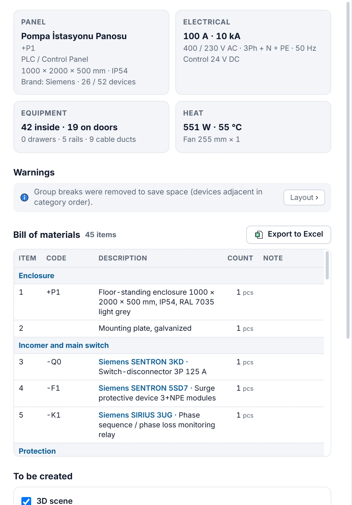 1234
- Summary — panel, electrical data, equipment, heat.
- Warnings — the button on the right goes to the step of the problem.
- Export to Excel — .xlsx with three sheets.
- Bill of materials — brand and series; no order number.
- Warnings: all errors, warnings and information messages; the button on the right goes to the step of the problem. Examples: does not fit — add a section, enlarge the panel or reduce the spare space, control height, button colors, insufficient depth, an MCC drawer that does not fit, rated current above 630 A.
- Bill of materials: item, device code (
-Q0,-F1…), description, quantity, note; divided into groups. Export to Excel writes an .xlsx with three sheets: Bill of materials, Panel data, Heat calculation. - To be created: 3D scene (a new 3D screen; Screen name, Doors open, Place a wall behind it), 2D view page (front and interior views, dimensions, title block; 1 mm = 1 pixel), 2D bill of materials page. The default names have the form
Pano_P1,Pano_P1_Gorunus,Pano_P1_Malzeme(from the panel code; if a name is already used,_2is appended).
Click Create. If there are unresolved errors, you are asked to confirm: devices that do not fit are not placed in the scene but remain in the bill of materials. In Studio, the creation is a single undo step (Ctrl+Z). The first screen created opens, and a summary of what was done is displayed.
- The design is stored in the project; Tools›Panel design wizard… opens it again. When you save the project, the design is written to the file as well.
- When creating again, the wizard uses the same screens and deletes and recreates only the objects it built itself. Objects that you added manually to these screens later remain; manual changes you made to the wizard's objects are lost.
- Delete design from project deletes only the design; the screens already created remain.
Limitations and points to note
To place panel objects manually without the wizard, see Panel components and DIN rail snapping; for the resulting 3D scene, see 3D screens.